A Brief Analysis of MMU Waterline Settings in RDMA Network
发布时间:2024-10-14 14:16:02来源:互联网
RDMA (Remote Direct Memory Access) has been widely used in data centers, especially in AI, HPC, big data, and other scenarios, due to its high performance and low latency advantages. To ensure the stable operation of RDMA, the basic network needs to provide end-to-end lossless zero packet loss and ultra-low latency capabilities, which has also led to the deployment of network flow control technologies such as PFC and ECN in RDMA networks. In RDMA networks, setting the MMU (Memory Management Unit) waterline appropriately is crucial for ensuring losslessness and low latency. This article will explore RDMA networks and analyze various strategies for configuring the MMU waterline based on real-world deployment experiences.
What is RDMA?
RDMA (Remote Direct Memory Access), commonly known as remote DMA technology, is created to solve the delay in server-side data processing during network transmission.

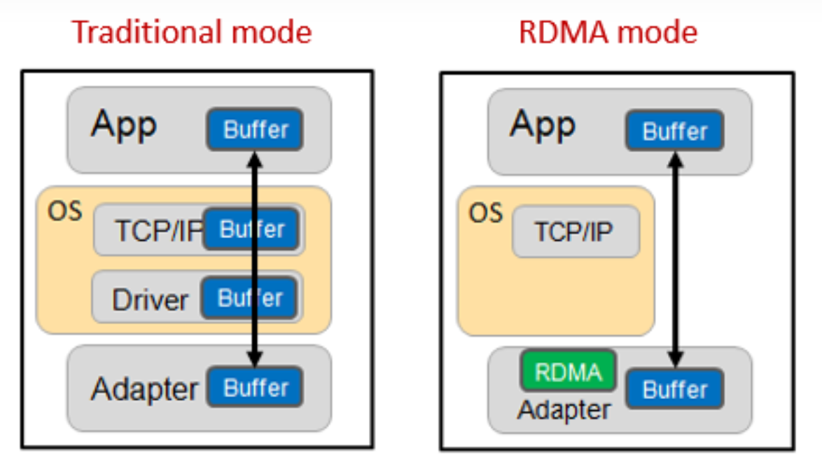
▲Figure 1 Comparison of working mechanisms between traditional mode and RDMA mode
As shown in the figure above, in the traditional mode, the process of transmitting data between applications on two servers is as follows:
● First, the data must be copied from the application cache to the TCP protocol stack cache in the kernel;
● Then copy it to the driver layer;
● Finally, copy it to the network card cache.
Multiple memory copies necessitate repeated CPU intervention, leading to significant processing delays of up to tens of microseconds. Additionally, the CPU's heavy involvement in this process consumes substantial performance resources, which can adversely affect normal data computations.
In RDMA mode, application data can bypass the kernel protocol stack and write directly to the network card. The significant benefits include:
● The processing delay is reduced from tens of microseconds to less than 1 microsecond.
● The whole process requires almost no CPU involvement, saving performance.
● The transmission bandwidth is higher.
RDMA’s demands on the network
RDMA is increasingly utilized in high-performance computing, big data analysis, high I/O concurrency, and other scenarios. Application software such as iSCSI, SAN, Ceph, MPI, Hadoop, Spark, TensorFlow, and others have started to implement RDMA technology. For the underlying network that supports end-to-end transmission, low latency (in the microsecond range) and losslessness are the most critical indicators.
Low latency
Network forwarding delay mainly occurs at the device node (optical transmission delay and data serial delay are ignored here). Device forwarding delay includes the following three parts:
● Store-and-forward latency: chip forwarding pipeline processing delay, each hop will generate a chip processing delay of about 1 microsecond (the industry has also tried to use the cut-through mode, and the single-hop delay can be reduced to about 0.3 microseconds).
● Buffer cache latency: When the network is congested, packets are cached and wait to be forwarded. In RDMA networks, larger buffers are generally beneficial, but a reasonable buffer size is still required.
● Retransmission latency: In the RDMA network, other technologies are used to ensure that packets are not lost, so this part will not be analyzed.
Lossless
RDMA can transmit at full rate in a lossless state; however, once packet loss and retransmission occur, performance can drop sharply. In traditional network modes, the primary method to achieve no packet loss is through the use of large buffers. However, as mentioned earlier, this approach conflicts with the goal of low latency. Therefore, in an RDMA network environment, the objective is to achieve no packet loss while using smaller buffers.
Under this restriction, RDMA achieves losslessness mainly by relying on network flow control technology based on PFC and ECN.
Key technologies of RDMA lossless network: PFC
PFC (Priority-based Flow Control) is a queue-based backpressure mechanism that prevents buffer overflow and packet loss by sending Pause frames to notify the upstream device to pause packet transmission.

▲Figure 2 Schematic diagram of PFC working mechanism
PFC allows you to suspend and restart any of the virtual channels individually without affecting the traffic of other virtual channels. As shown in the figure above, when the buffer consumption of queue 5 reaches the set PFC flow control waterline, PFC back pressure will be triggered:
● The local switch triggers a PFC Pause frame and sends it back to the upstream device.
● Upstream device receives the Pause frame, will pause sending messages in the queue and cache the messages in the Buffer.
● If the buffer of the upstream device also reaches the threshold, Pause frames will continue to be triggered to exert back pressure on the upstream device.
● Finally, data packet loss is avoided by reducing the sending rate of the priority queue.
● When the buffer occupancy drops to the recovery waterline, a PFC release message is sent.
Key technologies of RDMA lossless network: ECN
ECN (Explicit Congestion Notification): Explicit Congestion Notification is a relatively old technology that was not widely used until recently. This protocol mechanism operates between hosts.
ECN activates when a message encounters congestion at the egress port of a network device, triggering the ECN watermark. The ECN field in the IP header is then used to mark the data packet, indicating that it has encountered network congestion. Once the receiving server detects the ECN marking, it generates a Congestion Notification Message (CNP) and sends it to the source server. The CNP contains information about the flow that causes congestion. Upon receiving this notification, the source server reduces the corresponding flow-sending rate to alleviate congestion at the network device, thereby avoiding packet loss.
From the preceding description, we can understand that PFC and ECN can achieve zero packet loss in the end-to-end network by setting different watermarks. The reasonable setting of these watermarks is the refined management of the switch MMU, which is the management of the switch buffer. Next, we will analyze the PFC watermark setting in detail.
see more: https://www.ruijienetworks.com/support/tech-gallery/a-brief-analysis-of-mmu-waterline-settings-in-rdma-network
免责声明
【慎重声明】 凡本站未注明来源为“默认站点”的所有作品,均转载、编译或摘编自其它媒体,转载、编译或摘编的目的在于传递更多信息,并不代表本站赞同其观点和对其真实性负责。 如因作品内容、版权和其他问题需要同本网联系的,请在30日内进行!